Reconstruction of atom probe data
The unique feature of atom probe tomography is the reconstruction of the specimen volume from the obtained dataset, with atomic resolution and chemical information. This becomes possible, because for each evaporated atom the time of flight, the impact position on the detector and the respective voltages are stored. From this dataset, a three dimensional model has to be reconstructed. Different approaches are available for reconstruction [1]. A reconstruction algorithm based on a point projection model is commonly used. The tip itself is modeled hemispherical. This assumption is not always valid and is object of current research on improved reconstruction algorithms. The x and y position within the sample are reconstructed from the impact positions xD and yD on the detector (Figure 1), while the depth scale is calculated by the sequence of evaporated atoms. A constant volume is assigned to each individual atom species.
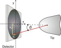
From the impact position, the detection angle υ can be calculated from the relation
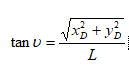
The incident angle is correlated with the real crystallographic angle by the image compression factor κ. This is a tribute to the assumption of a point projection. The true projection centre is in-between a point projection and a stereographic projection and causes a compression of the observable angles between crystallographic poles. This compression factor can be determined by careful analysis of field ion images. For the used instrument, the compression factor was determined to 0.58 and therefore the observed angle can be corrected by

The originating coordinates of the atom at the tip surface can be calculated by
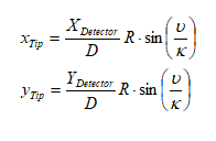
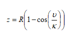
with D = (X2 Detector+Y2 Detector) 1/2. While the x and y coordinates are now identified, the z coordinate according to Figure 2‑7 remains unknown
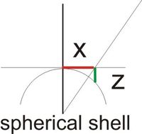
But with the assumption of a hemispherical shape, the z position can be calculated using
the eroded volume. In principle, the shell has to be moved one atomic distance, if all lattice positions are occupied. The number of positions can be calculated from the normal density of the measured material. But the detection efficiency of modern detectors is just around 50 %, so a shell will always not be fully occupied. How should the shell be moved?
The solution of this problem is rather simple. A constant volume is assigned to every atom species. Then the shell is moved by a small, infinitesimal distance dz0 every time an atom is detected. The sequence of detected atoms is a natural depth scale, because atoms can only evaporate directly from the surface.
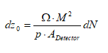
where Ω denotes the average volume per atom and p the detection probability of the detector wit the detection area A Detector. The magnification M can be derived from

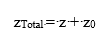
The magnification M is determined by the distance L between tip and detector and the radius R of curvature, which is a function of the applied voltage. Finally the correct z coordinate for a single atom is the sum of eq. 2‑13 and eq. 2‑14
To be able to reconstruct the obtained data correctly the tip radius R has to be known.
Two different ways to determine R are often used. A very common way is to calculate R using eq. 2‑1. A constant evaporation field strength E is assumed and thus the radius can be determined [2]. This assumption is mostly valid for pure materials or alloys made of constituents with similar evaporation field strengths. Problems may occur in heterogeneous materials or at interfaces, resulting in reconstruction artifacts. If the evaporation field strength varies, the shape of the tip will vary suddenly, leading to a wrong density at the interface. This is very critical for multilayer systems like GMR sensors. A different approach makes usage of geometrical considerations. [Jeske2001]. The tip radius is determined omitting the varying evaporation field strength.
FreeShape Algorithm
Density Algorithm